|
|

|
Making - Drive Shafts! With Brass - Tubing & Rods ( Designed for R/C Workboats & Ships ) "Not Meant For Use in Speed & Race Boats!"
This Idea is very simple and uses the - "Basic Three Brass Tube - Building Method" of construction. Each of the required three different sizes of Brass Tubing, must fit ( One inside the Other ), like a Telescopic Antenna. The size of the tubing = used, depends on what your model needs in a drive shaft? To determine this, look at your Wheels = PROPELLERS .... "What diameter of "Drive Shaft" do they Require?" By measuring the diameter of the shaft hole in the prop, you simply choose the correct diameter of brass tubing or rod, to make the "Drive Shaft", then work up a couple sizes to complete the system. CRITICAL ITEM = NEVER - OMIT!!! ...... ( The 2 - 1/2" Long - SLEEVE'S ) installed in each end of the Housing Tube are critical items. They must be installed for this drive shaft system - to operate properly. THE SLEEVES .... act as Bearings & Grease Seals = Or Spacers, between the "Drive Shaft" itself and the Housing tube. If omitted, the drive shaft will overheat - as it turns inside the housing, swell-up & seize tight and ruin the entire drive. Brass expands under heat & friction, so the 2 sleeves reduce this effect to absolute minimum's and must be installed. They also provide a space ( Or Gap ), for the lubrication grease, which acts as the shafts = water proofing seal, between it and the Housing. The length of the Drive Shaft - Itself, makes little difference ( Short Or Long ), the system works and is easily made to virtually any length required. "With Or Without" a Gear Drive, but the drive should always be equipped with a flexible motor to shaft = coupling, like the Dumas Motor/Drive Couplings for example. NOTE...... To fill the drive shaft = with grease, simply purchase a small "Hobby Syringe" and fill it with ordinary "Axle Grease", or any general purpose "Automotive Grease" like they use to to lubricate a vehicles - ball joints .... NOTE! = Never Use" = Heavy Oils or Petroleum Jelly, in this drive shaft system = THEY WON'T WORK! Drive Shaft Making - Parts List #1 ... ( 3 ) Lengths of Brass Tubing ... K & S brand - for example, available from most any hobby shop or hobby supplier parts catalog. ( Sizes of tubing required, depends on diameter of your already purchase - Propeller and its -- Drive Shaft Hole Dia. Then work - up, two more sizes in tubing to create the 2 Sleeves and the Shaft Housing ..... That's It! ) #2 ... ( Solder = 60/40 Rosin Core - Electronic Solder, Plus cleaning Paste & Brush and a Damp Sponge to clean your solder Iron or Solder Gun - Tip. #3 ... Lube Grease, can be purchased in "Throw Away" tubes for hand operated Grease Guns .... Purchase at Wal-Mart or Local - Auto Parts .... Common gun grease, is what mechanic's use to lube fittings on your car / truck or tractor- drive shafts and other grease fittings. #4 ... ( 1 ) Hobby Syringe, filled with Grease to lube your shafts. Keep it handy in your r/c tool box, and periodically lube drive shafts, after several runs, to insure their well greased and water sealed - at all times! REQUIRED LUBRICANT= Ordinary - Automotive Grease or Axle Grease ..... "Use No Other types or Petroleum Jelly or Oils - inside this drive system. Only grease like those used to lube a car / truck or farm machinery, purchased from any auto parts or Wal-Mart Store. And be sure to purchase a small "Hobby Syringe" to fill with grease and keep it handy - in your tool box, to keep your shafts lubricated periodically. Just insert the syringe - down the "Grease Tube" on the drive shaft, and add a small amount of fresh grease, after a few runs, to keep the systems water tight! Break- In Method..... Use a bench vice to hold the new drive shaft - firmly. Then use a spare dc motor connected to a battery - to turn the drive shaft, after you have filled the housing with fresh - Grease, using the hobby syringe. As the shaft - turns and spins, for the very first time, the new grease will instantly start to look - dirty. And may begin to ooz - from each end of the housing.... RELAX, That is Normal. But as soon - as it stops oozing out, insert the syringe and add a few more drops of grease - as the shaft is spinning, so it fills any voids with more grease. Meaning any open space the grease didn't reach, when you first assembled the parts. Once the shaft is broken-in, by running it for several minutes in time .... "Re- lube again and clean off - any excess grease from the outer - housing, prior to installation into the hull. ( Use "Paint Thinner or Acetone" with an old rag ), then rough sand the housing. in areas where it enters or exits - the hull, to insure the glue - used, will hold it - firmly without any Hull - Leaks! ) INSTALLATION - OF NEW SHAFTS ..... Mount the Shaft into your hull with heavy set epoxy glue, designed to withstand water to insure it never vibrates - loose or leaks. Here I suggest everyone use of J-B WELD EPOXY WELD ..... This glue is purchased at most any - Auto Parts Store / Wal-Mart or Hardware store. Its a 50/50 Epoxy mixture that withstands constant moisture and doesn't come loose in automotive use, under water or high heat conditions. Other brands of epoxy like hobby brands of "50/50 Hobby Epoxy in 5 to 30 minute types as most use in this hobby, don't withstand moisture or constant vibration and it will easily comes Loose or break down! ... So Be Warned, if ya use that sort of glue = and it fails ... Don't say - I Didn't Warn Ya! Shaft Building Tools - Required #1 ... Dremel Tool & Bitts = Cut-off Wheel, Sanding Drum / Etc. ... to cut & shape parts. #2 ... Solder Iron ( 25 Watt ) or Solder Gun ( 50 /100 Watt ), plus solder gun- tip cleaning equipment and tools, or a small - Propane Hobby - Torch. #3 ... 60/40 Rosin Core - Electronic Solder and Soldering Paste to insure good welds on parts. #4 ... A small piece of 200 Grit - Sandpaper, to polish brass tubing - at all points to be soldered, prior to applying solder and final assembly. #5 ... Bench Vice - to hold parts, as their assembled. #6 ... Spare - Dc Motor & Battery / Jumper Wires & Drive Shaft - Couplings ), to break-in the New System before its installed into the hull! _____________________________________________________________________________
GEAR DRIVES Some - Like Them, Some Don't! ..... But Their all important in a model, when you have trouble slowing it down to a crawl during those close-in critical maneuvers and lets face facts here = Workboats ain't = Speed Demons! Gear Drives also help keep your dc motors - Running Cooler Too!! So the few shortfalls that gears - have, are worth the hassle in my Opinion. And you'll find several links to sources of gears & belt drives on my Hobby Links Page. NOTE! .... Plastic gears are less noisy, than metal ones, but a belt drive is the smoothest system, provided you have the space to install them? So it depends on how much you want to spend, since plastic gears or most usually cheaper then metal or brass gears. Besides - Metal Gears make a lot of noise, which can cause RF radio interference sometimes. Picking A Gear Drive The best brands or types of Motor - Gear Drives, will have "Nylon Gears" to reduce further shaft or motor noise! Metal Gears are always much-more noisy, and also cause a great deal RF or radio control interference. Here again, a "Belt Drive" is even better, because their smoother running and also easier to install, but usually cost more. Whether purchased or Made = All Scratch, both systems will reduce rpm motor speeds and also further reduce the current loads on the motor, battery and speed control to more manageable points. So that means longer runs, and everything stays cooler and the battery lasts a lot longer. The ratio of the drive, meaning its two measurements from Engine to Shaft in turn speeds, can basically range between 2 to 1, to over 6: to 1 ratios, which is shown as 6:1 in the systems information. Here, the usual ratio's most often used are 3: to 1, meaning the motor turns 3 times, to ever single turn of the propeller. Unless it needs more reduction, like in the case of a "Paddle Wheeler" for example. These gear driven system, usually report the shaft speed at somewhere close to 100 Rpm's, which is about true speeds for a real steamboat - paddlewheel. So a drive that provides about 120 Rpm's, might be a good choice, or maybe one that says it puts out - 85 Rpm's as another example in trade off's, depending on what voltage its going to be operated at. Here, something which provides 120 rpm at 12 volts, won't work to well at 6 volt, or 7.2 volts, because the drive is to slow. But a drive motor that runs at 200 rpm, at 12 volts, may be perfect at 6 volts, while just a little fast - at 7.2 volts, so it will work - Right?.....Yep!....Yer getting the Picture Now! _______________________________________________________________
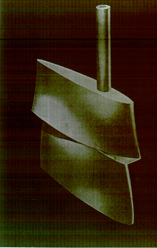
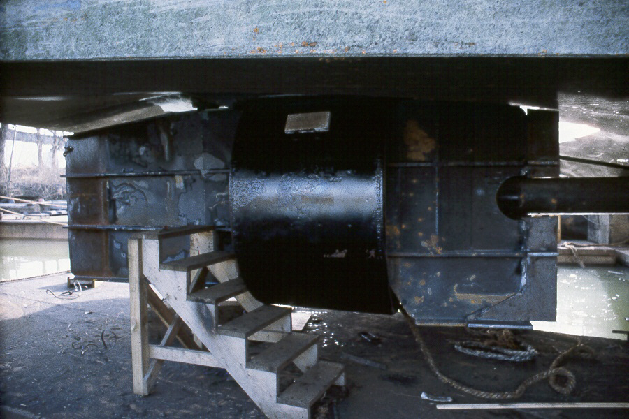
RUDDERS - They Ain't All The Same! The average person seldom considers - rudders, all that important to a vessel, since all boats have to have them - Right! .... Well its a bit more complicated then you think. Rudders can be very sophisticated systems, and even high tech, on even a small Workboat in some cases. And once you see and understand the unique ways a rudder can be shaped - to do some very odd things.... Like a Wing does on an airplane. It all starts to make a lot of sense and workboats becomes even more interesting - in how unusual and unique - these boats, really Are! Tap Photo To Enlarge
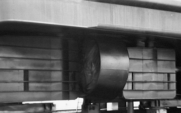
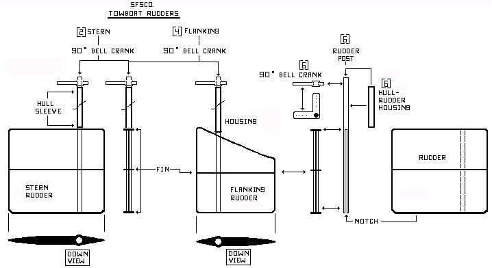
Two Types of Rudder Systems! FLANKING & STERN.... Both systems are individually - operated, on real boats, but in this case, via R/C Radio Control in Model boats, we can choose several ways to achieve this effect. But first, you need to understand rudders - on these boats, which are not typical, or like those used on other vessels. Because towboats typically have 3 rudders = per shaft ..... And they're are a lot of - Single Screw's out there - so remember this fact. A Twin Screw typically has a total of 6 rudders - in all. And a Triple Screws, or Quad Screw towboat will have a total of 8 to 12 rudders - Respectively. Such large numbers of rudders does sounds - Rather Confusing, and difficult to imagine for some modelers. But their critical parts in what makes these boats - So Unique!...... "So They Gotta Have Them to be - Real + TOWBOATS!!" Tap Photos To Enlarge
Tap Photo To Enlarge
_______________________________________________________________
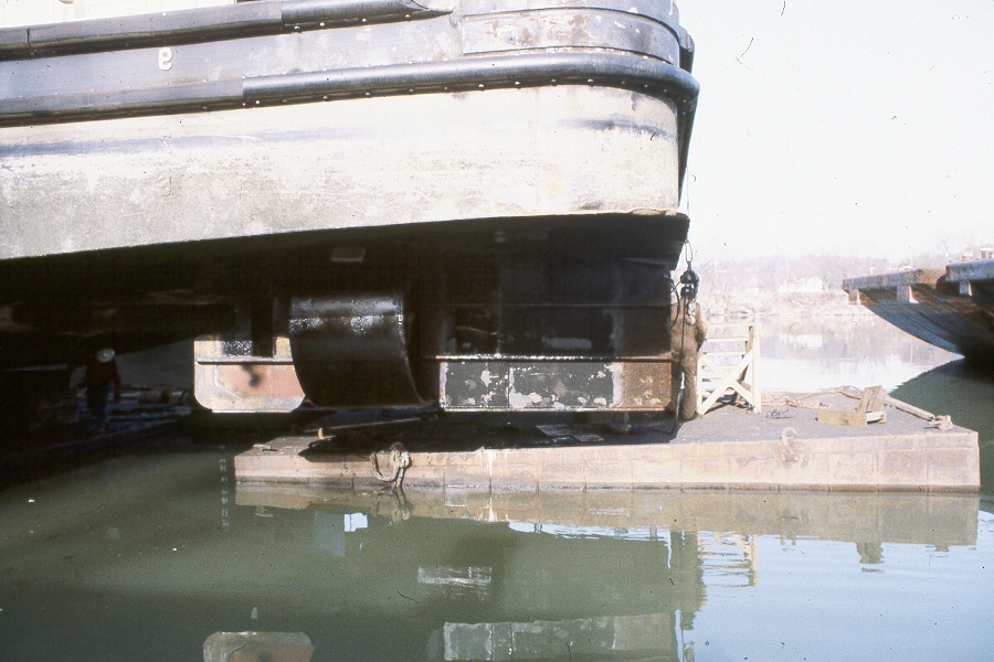
Break-Off or Break-Away = Rudders ( See Also = Barn Door & Contrguide Rudder Details - Below ) As strange as this sounds, rudders and their steering shafts, can be designed to completely break-off, or have sections - that break - off, if their hit or damaged. Considering that a towboat hull is constantly being - run aground on shallow rivers, this idea makes lots of sense. Building such features into a rudder, is accomplished by making the rudders post - itself, in 2 sections. Naturally, the upper section of the rudder - is made from solid metals, but the lower section is designed to break off - If Struck By an Object. "Break Away - rudders", allow a vessel to continue service, but with reduced steering effectiveness. These rudders are welded with - Overlapping Joints, Or Bolt-On Sections, that create such effects using soft-bolts. Highly unique and towboats were the 1st vessels - to use them, which later led to these rudders being introduced into other realms of ships and boats too.
Proper Rudder Positions - ON HULLS I simply can't stress this - enough, because rudders improperly positioned on a hull, make their effect on the boat, almost = USELESS! Tap Drawing to Enlarge
Tap Drawing to Enlarge
Parts Required - Solder Gun Solder = 60/40 Electronic Type or Silver Solder & Solder Paste Sandpaper Dremel Tool & Bits Brass Sheets, Tubing & Rods NOTE!.... Brass or Copper Materials can be used to make these parts, available from K & S Metals ( See Hobby Links Page ). If Copper = is used, it must be polished - before soldering, then smooth all parts with sandpaper or Dremel tool - for finishing. __________________________________________________________________
Last Updated
On 06/29/23 .
With
|
 TM
TM