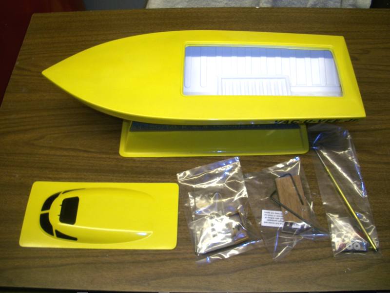
Vac-U-Vee Jr.™
20" Deep Vee RC Boat Hull Kit Straight Shaft
Build Page
Click on the photo to enlarge.
Assembled with Loctite Polyurethane Roof Sealant in these photos. Their white colored Polyurethane Window & Door Sealant has the same properties and looks better against the white plastic interior of the kit. Other sealants or adhesives can be used.
 |
 |
| Loctite PL S40 like this in some stores. | The latest new packaging for 2021. |
Additional installation examples are shown on the Flex Build page where epoxy with filler is used as an adhesive.
 |
 |
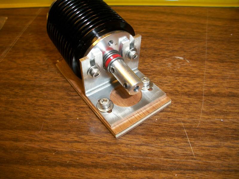 |
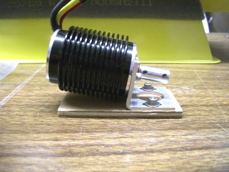
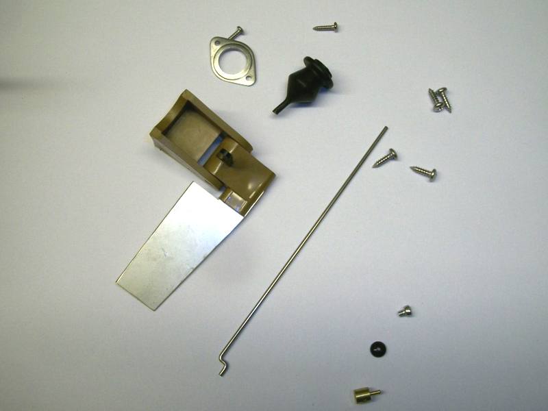
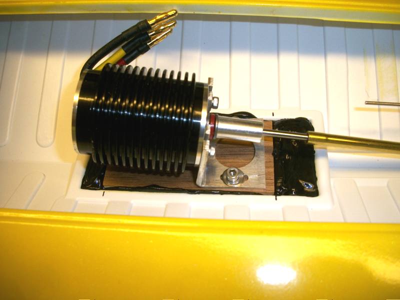
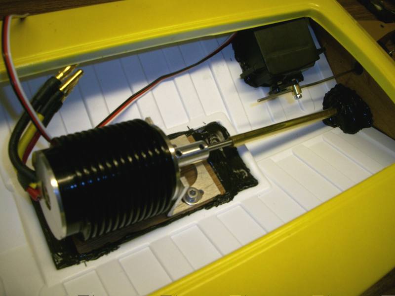
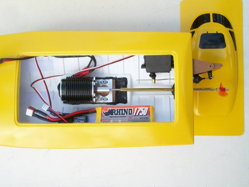
| Kit with Cracker Rudder and Drive | 12S air-cooled car motor with thrust bearing installed with 1/8" coupling. | Bolted to motor mount. |
 |
 |
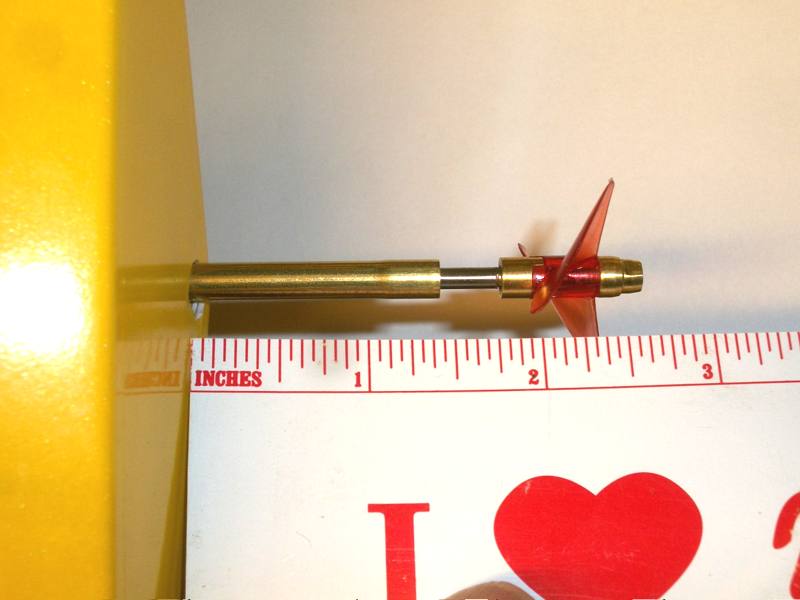 |
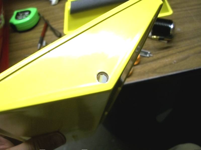
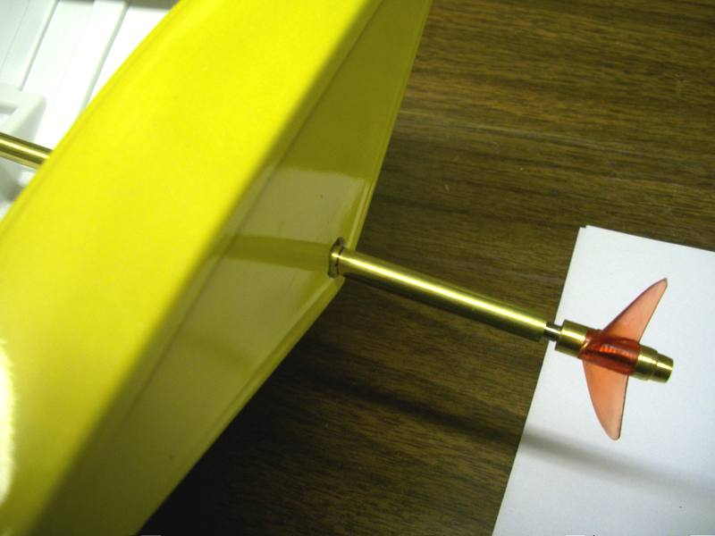
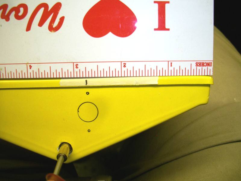
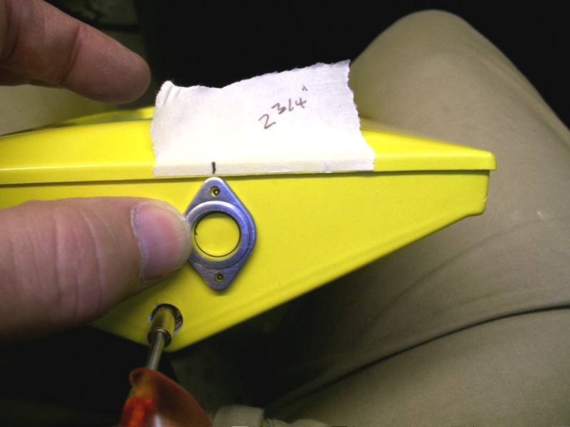
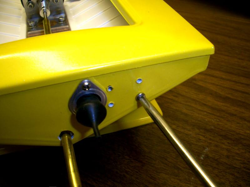
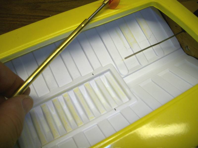
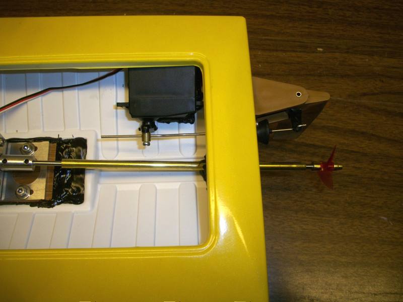
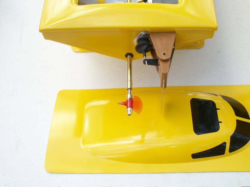
| The angle can be adjusted with careful force. | Hole in transom. A step drill works well. On the inside, the hole is about 1/8" from the bottom of the liner. | 2 inches to the leading edge of the prop, 2-1/4" to the blade center, works well. Keeps the prop under water at start-up. |
 |
 |
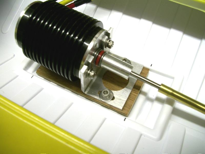 |
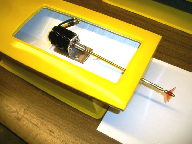
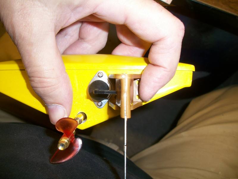
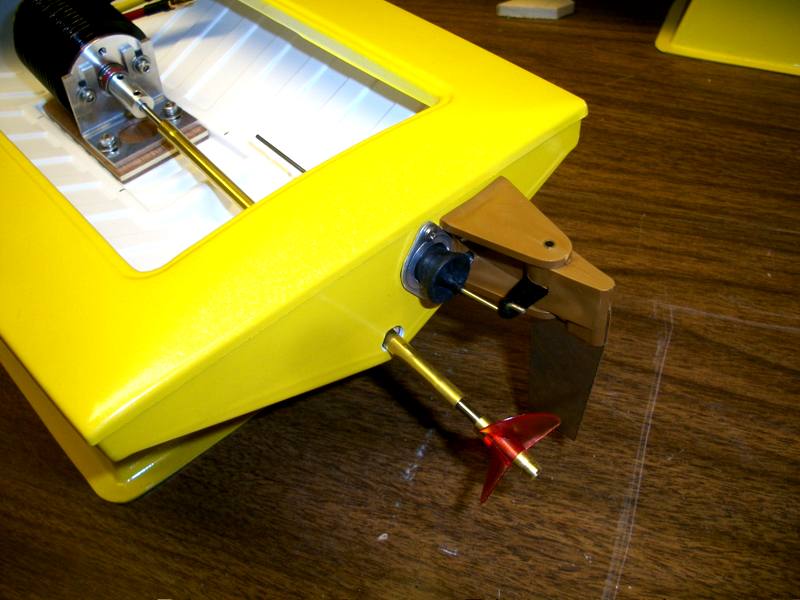
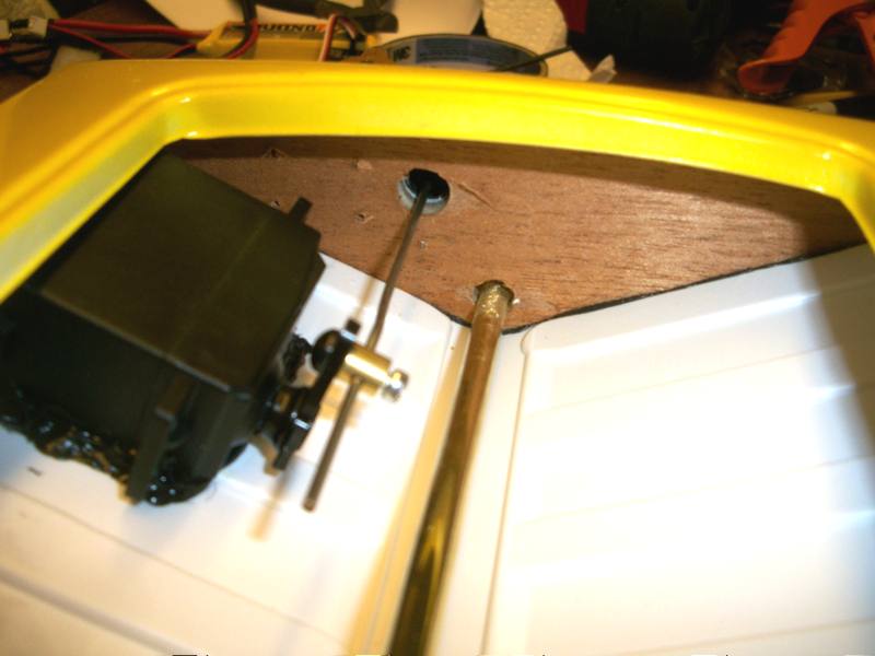
| Drive set in place for angle and fit check. The shaft is tightened to the coupling. | Rudder Assembly. | Once you locate the prop from the transom, mark the position of the motor in the motor recess of the hull liner. |
 |
 |
 |
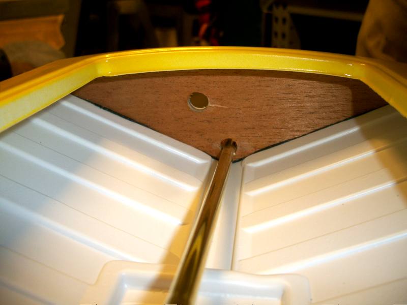
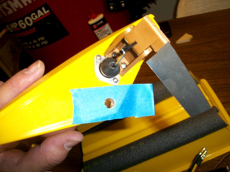
| Be sure to leave a space between the stern tube and the prop drive dog. | Location of rudder pushrod hole. | Bru-Line rudder boot fitting. |
 |
 |
 |
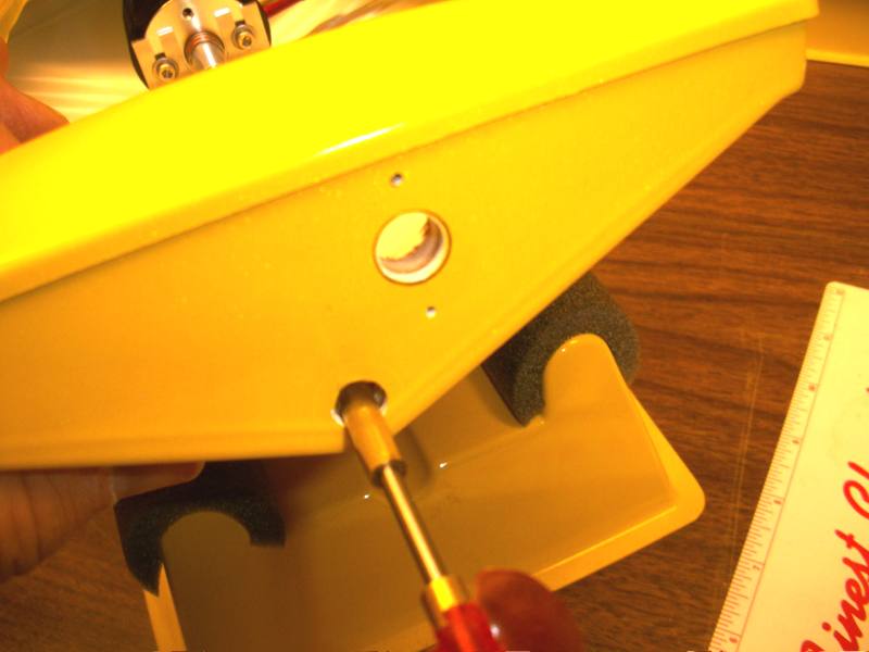
| Drilled hole with a step-drill. No rush. | Holes from the inside. | Temporarily hold rudder in place. Mark the 4 holes for the rudder bracket. |
 |
 |
 |
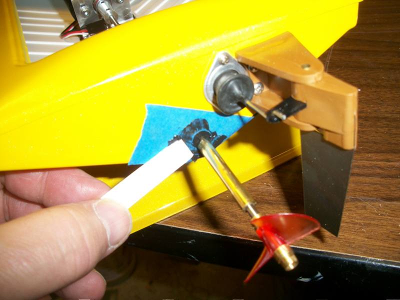
| Drill the 1 holes with a 1/16" bit. Insert screws to thread the holes. | Install the rudder pushrod as shown, from the bottom of the rudder arm. | Put a little grease on the rudder pushrod and push through the boot as you set the rudder against the transom. Attach with screws. |
 |
 |
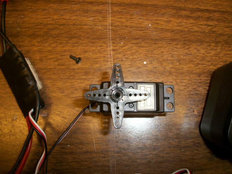 |
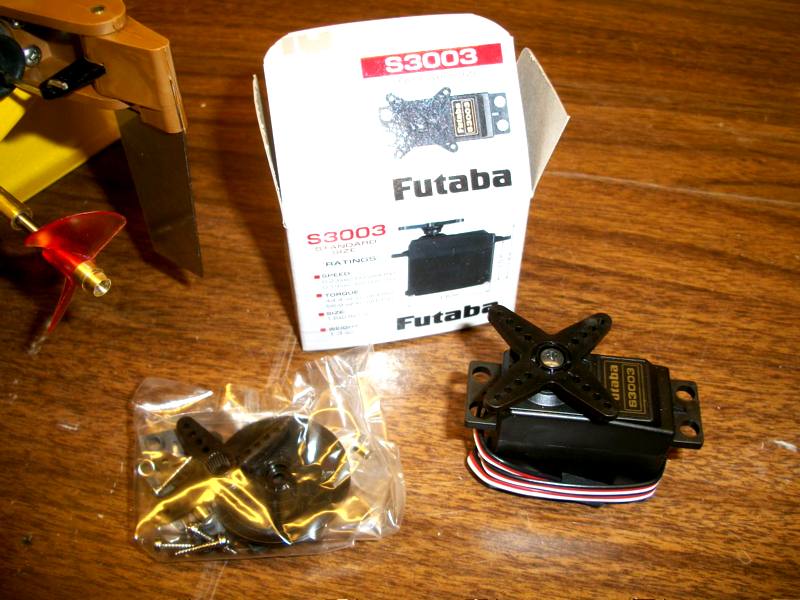
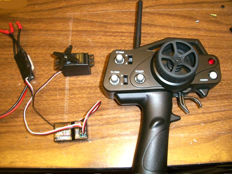
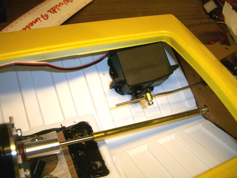
| Standard Futaba servo. | Center the servo. Radio and receiver ON. Wheel and adjustments centered. | Remove the servo arm and re-install in this position so it is now centered with the radio. Note that the rudder wire comes out on the left side. |
 |
 |
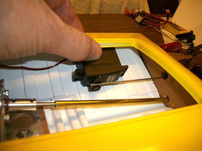 |
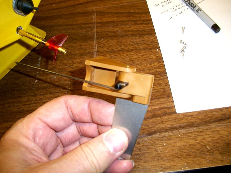
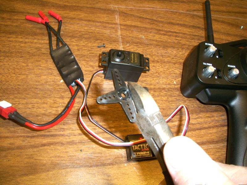
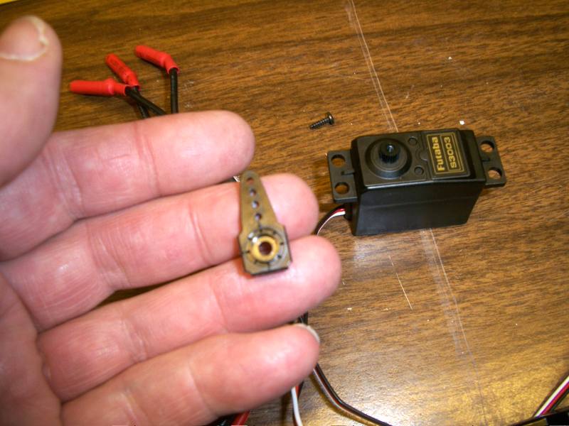
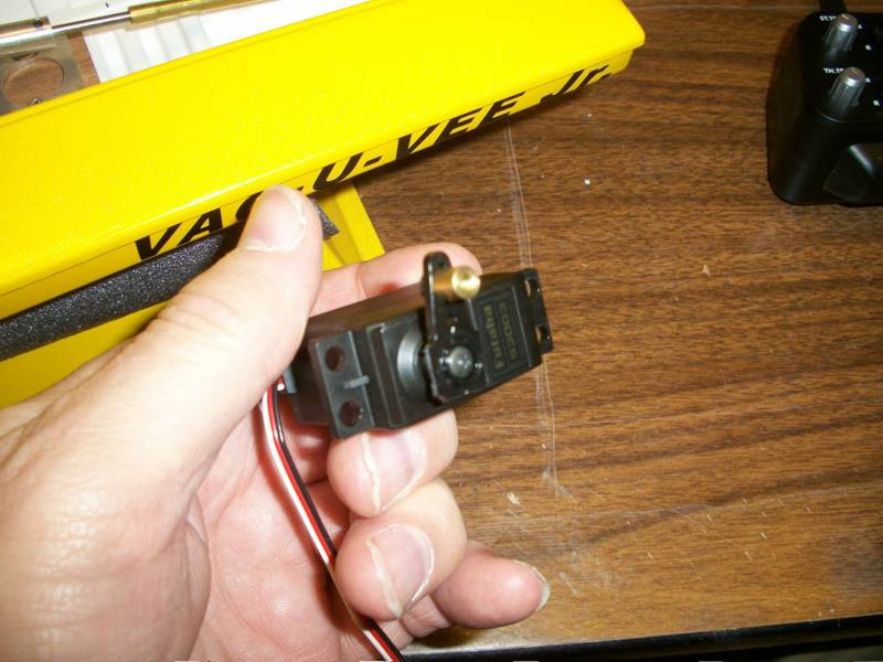
| Clip off the left, right, and bottom arms. | Trimmed arm. Install on servo with screw. | Locate the servo to the hull. Determine how to bend the rudder pushrod to align with the 2nd hole from the end of the arm. |
 |
 |
 |
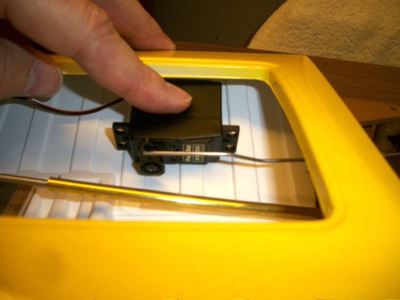
| Check again. Note the slight Z bend in the pushrod. | Attach the EZ-Connector to the rudder arm 2nd hole from the end. | Set the rudder in place. Check the alignment. There should be no binding. The pushrod should be centered in the transom hole. Mark with pencil. |
 |
 |
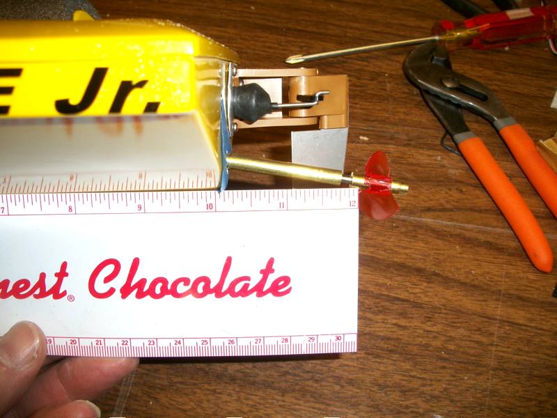 |
| Remove the servo. Sand the floor where it will be glued. Score or sand the bottom side of the servo. Sand the motor tray bottom, and the tray recess. Sand the stern tube in front of the transom mark. | Tape over the transom hole. | Check again. The ruler is set to the bottom of the keel. You want it to intersect with the propeller shaft here. |
 |
 |
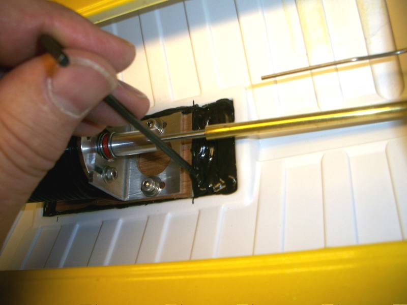 |
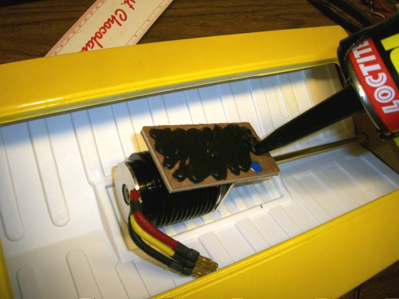
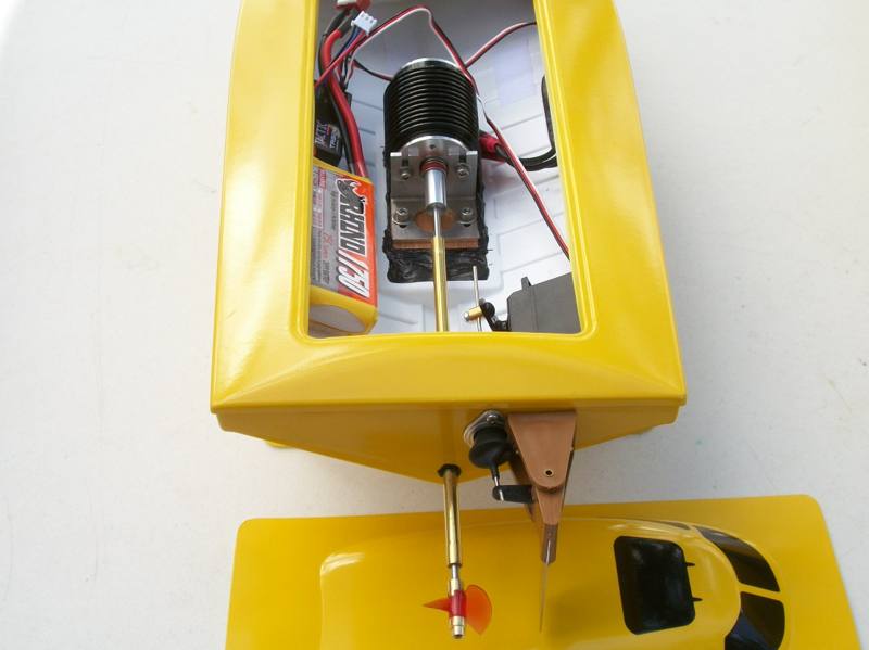
| Apply sealant to the motor mount base and into the recess. | Set the motor in place checking on the alignment of the shaft. | Push sealant around the base. |
 |
 |
 |
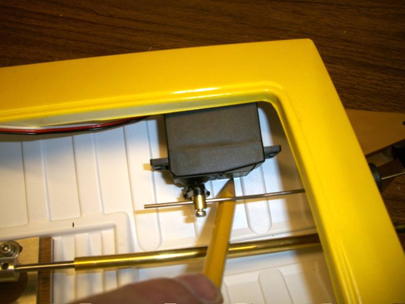
| Bed the servo into the sealant. | At this point, the stern tube will still slide up and down on the 1/8" shaft. | Move the stern tube to it's proper location, some space between it and the prop drive dog, then apply sealant to secure the stern tube. |
 |
 |
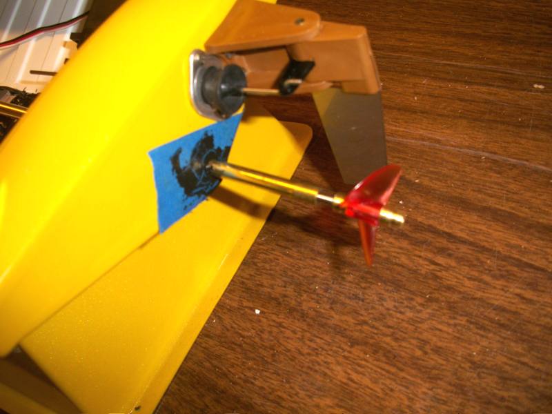 |
| Use a plastic scrap to smooth out the sealant where it comes out of the transom. Make sure it is on all sides of the stern tube. Rotating the stern tube will distribute the sealant. | Before the sealant cures, check all measurements. If the servo wants to move, you can tape it in place. Usually not necessary for this sealant. | Check for the proper length of the stern tube and shaft, out of the transom. |
 |
 |
 |
| Finished installation. Battery on the left, ESC (hidden under the side of the opening) on the right, receiver on the left can balance the boat well. | Check for a centered rudder. Adjust with the radio rudder trim adjustment if needed. | Let the sealant cure for 48 hours before using. |
 TM
TM