Vac-U-Tow 2™
Length: 21.5 in. Beam: 6.5 in. Draft: 1.6 to 2.0 in. Displacement: 4.5 to 6 lbs.
1:48 Scale (1/4 inch = 1 foot)
(Servos shown on photo are not included.)
Twin-Screw Model Towboat Kit
( Model Pushboat Kit )
For Radio Control, Manufactured by Vac-U-Boat™
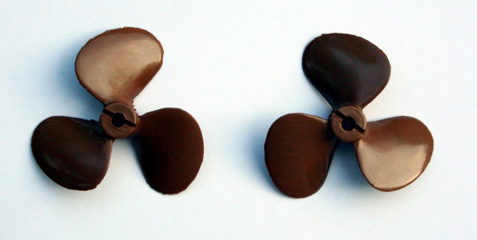
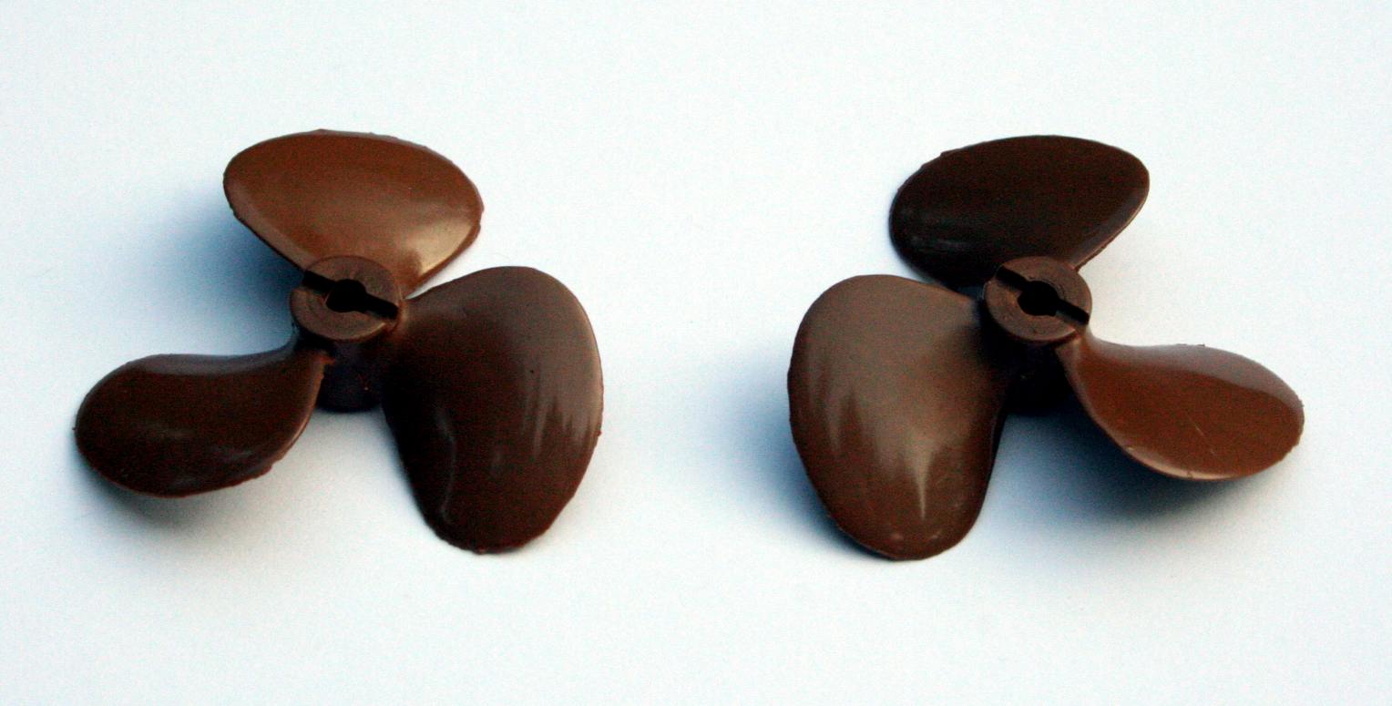
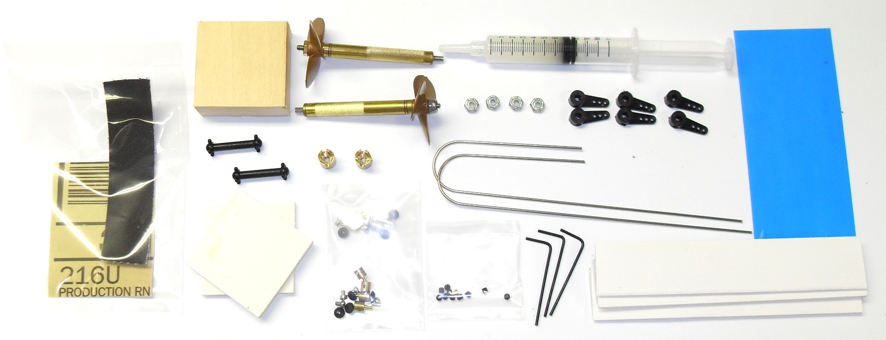
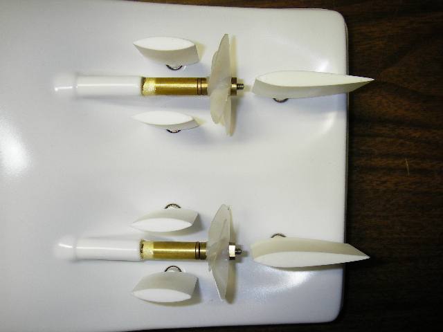
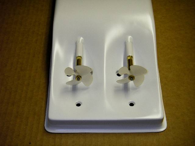
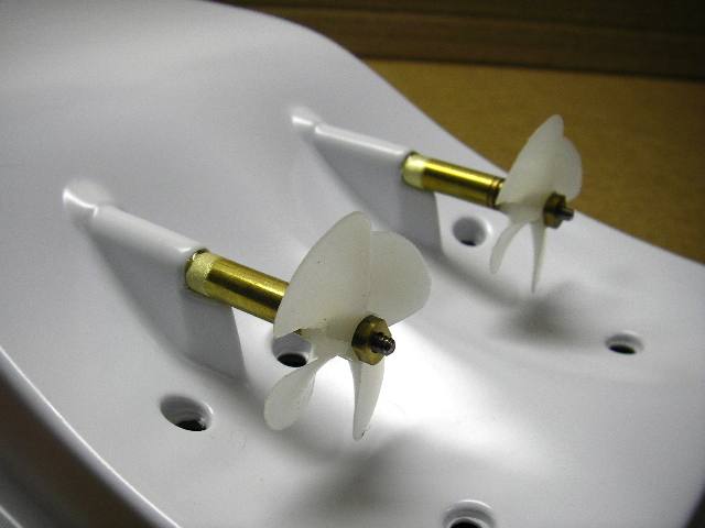
This kit ships with this set of counter-rotating 1-3/4" diameter bronze metallic plastic props.
Kits will be shipped with tip pages for installing the twin-drive system.
To build this model, follow the single-screw towboat instructions below.
The Vac-U-Tow 2 is a twin-screw version of the Vac-U-Tow. I don't recommend the twin-screw for just "more power". Running on 12 cells instead of 6, or a 3S LiPo instead of a 2S LiPo will give you that. The twin is best to simulate the actual handling characteristics of a modern real twin-screw towboat in handling barges or maneuvering on a river.
Now available in two TOPLESS TOWBOAT versions. Click HERE for details.
The kit contains all of the single-screw Vac-U-Tow parts plus a modified hull, liner, and a complete second drive system from motor to prop. Like the Vac-U-Tow kit, servos, batteries, or radio electronics are not included.
Discussion about setting up this boat with a 2-stick 4 or 6 channel radio:
With a relatively inexpensive 2 stick 4 or 6 channel radio, if you put the left motor ESC on the left stick forward/rearward movement, and the right motor ESC on the right stick forward/rearward movement, then put the left set of rudder/flankers on the left stick left/right movement, and the right set of rudder/flankers on the right stick left-right movement, you will effectively have two "gimbals" for directional force application (thrust vector) without a computer.
The only gap in the layout would be moving the sticks only left or right. Without a prop turning (forward/rearward movement needed for that) there is no thrust produced. However, if you move the right stick to the 1:30 position, you will get trust pushing toward 1:30 (right front). Then the left stick to 7:30 and you will get thrust to 7:30 (Left rear) and the boat may not move much because the two thrusts are pushing opposite of one another. Vary the angles and you can impart a twist motion to the hull. Adjusting the amount of thrust and the direction will let you pivot the hull from the bow, or the stern, you can crab sideways or do most things a real twin screw can do.
To crab left, left stick left lower, right stick left upper with a little more power to the left upper to compensate for the mass of the bow, an she will slide sideways.
This setup is a little different than the setup on Towboat Joe's site where the flankers are on one stick and the rudders on another. That setup is similar to real boats in that in the cab of a towboat, there are two large levers, one pair of them on each side of the pilot house so they can be operated while standing on either side of the house. The small lever is the flankers and the large lever is the rudder. All of the linkage to set it up that way left some slop due to the need for bellcranks and things that cost money...
My setup combines the rudder with the flankers and ties them into the thrust of that side's prop. This is more like the computer/servo controlled real boats that have a joystick on the helm to apply a thrust vector. It can make the twin screw towboat feel high-tech without the expense of additional electronics.
![]()
Single-Screw Vac-U-Tow Kit instructions for reference.
 |
Some photos of the development of the Vac-U-Tow 2 kit follow:
(All framed photos can be clicked to enlarge.)
Hardware bag for Tow 2 kit.
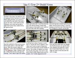
I still need to make a set of comprehensive instructions. In the meantime, a few prototypes I have shipped include these notes to accompany the single-screw version's instructions.
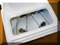
Modified the rear hatch opening for both the single-screw and twin-screw models. Rear hatch is raised 1/16" and has a full opening with a clear plastic window that can be taped in place for a transparent waterproof seal under the rear hatch cover.
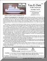
Click the photo below to view the instructions in a PDF file.
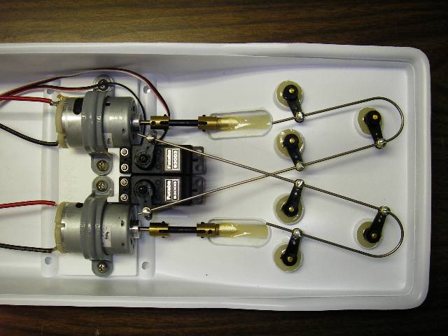
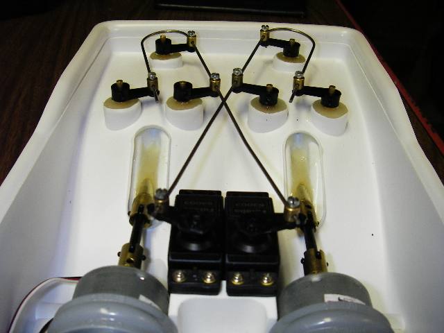
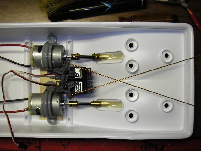
Makes all of the drawings & plans seem worthwhile. Elegant Simplicity. Two pushrods running 6 rudders. No linkage play or rudder slop. No wasted space. Minimal parts to fail. Pushrods are about 1/8" apart where they cross. No metal-to-metal contact that might create radio interference.
|
 |
 |
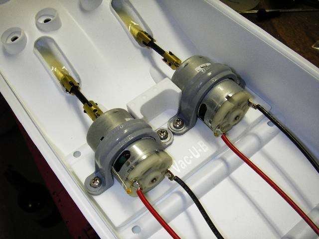
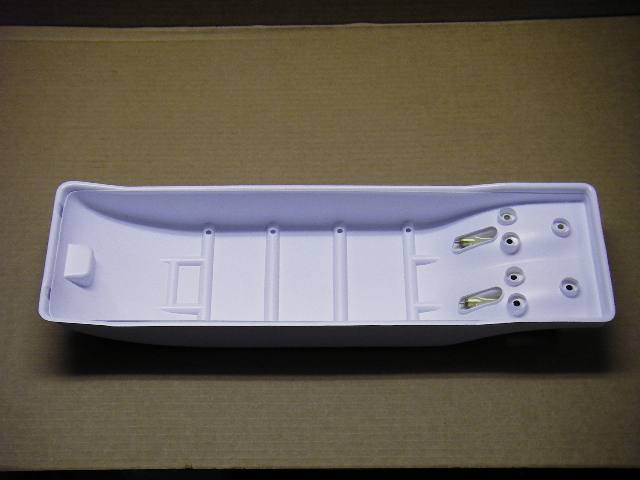
Twin-Motor/Servo tray is done and has a good fit. As soon as the epoxy cures, I'll mount the servos, rudders, & flankers and fit the pushrods.
 |
 |
Designing the motor/servo mount and pushrods for the rudders. The crossed pushrods will be insulated and spaced from each other to prevent metal-to-metal radio interference. The "factory" layout will be independent left and right rudder/flanker controls so you can control each motor and each set of rudder/flankers with a 2-stick 4-channel radio. It can be adjusted to tie the 4-flankers together and 2-rudders together by modifying the pushrod layout and adding two 90-degree bellcranks between each servo and each row of rudders.
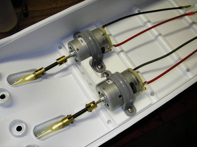
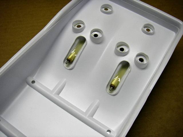
Hull and Liner test molds show a good fit. Machining the twin engine/servo mount. Building a first-prototype to confirm a good fit & finish.
 |
|
 |
 |
Hull done and test molds are good. Working on the Liner mold now. Once the liner is complete, I'll start milling a twin-motor/servo mount.
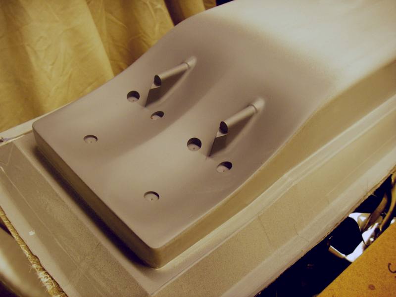
Lower hull mold almost complete. Have a few holes to drill and to mount it for test-molding. It is designed to use the same drive, rudders, and flankers as the single-screw Vac-U-Tow kit.
 TM
TM