Vac-U-Pickle
TMSmock Certified™ Hardware Build
Fullers 1" super strut bracket, short super strut .150, aluminum skid fin, 3.5" rudder, and .150 Hughy cable. If racing as an SSH "Super Sport Hydro", with the SV-27's motor/esc setup, a balanced and sharpened Octura X442 prop is recommended.
As of 2010, the turn fin made by Aquacraft for the UL-1 is recommended.
 |
 |
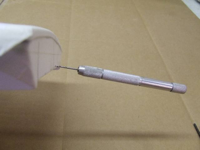 |
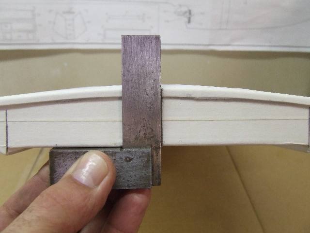
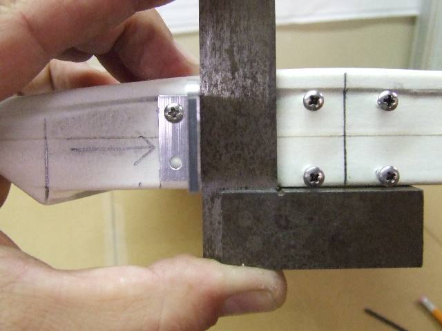
| Measure to the center of the transom and mark a square line. | Position the strut bracket and mark four holes. | Drill 1/16" strut mounting holes. |
 |
 |
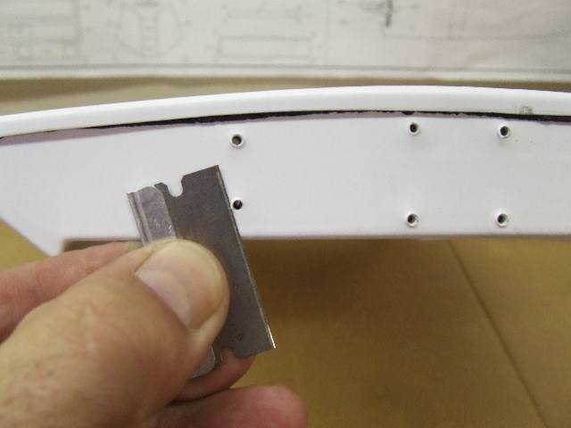 |
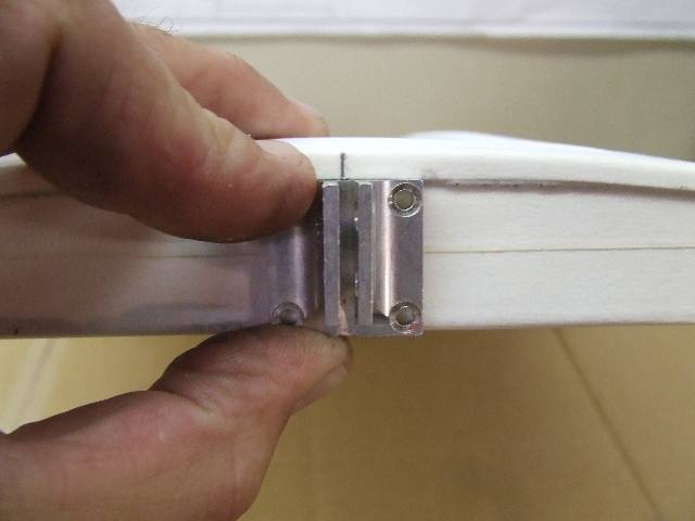
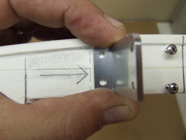
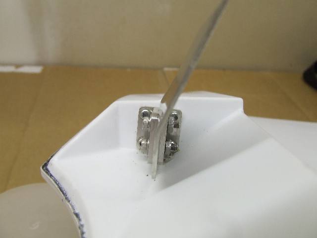
| Arrow marks the end of the port stringer (rib). Make sure the screws are to the right of that rib. | Install one screw, then use a square to adjust the rudder bracket before installing 2nd screw. | Trim the raised area around the hole for a flush fit. |
 |
 |
 |
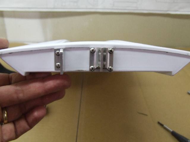
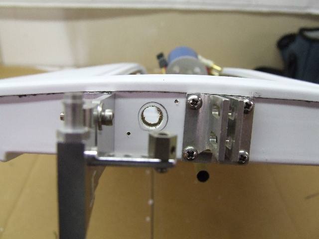
| Rudder and strut brackets attached. The initial
adjustment for the strut is 3/4" from the center line of the strut to
the bottom of the boat. About one degree of down angle to the prop. |
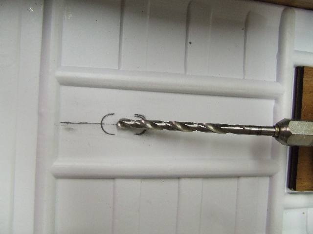
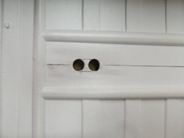
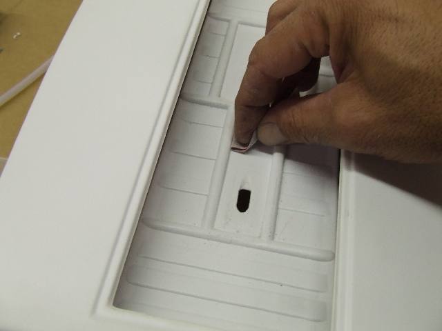
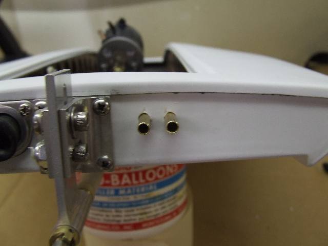
Mark a center-line in the pass-through well. Attach 5mm motor-to-flex shaft coupling. Adjust motor mount to forward limits. Attach a matching drill bit to the coupling to locate the hull pass through. | Drill two holes at each end of the marked oval. |
 |
 |
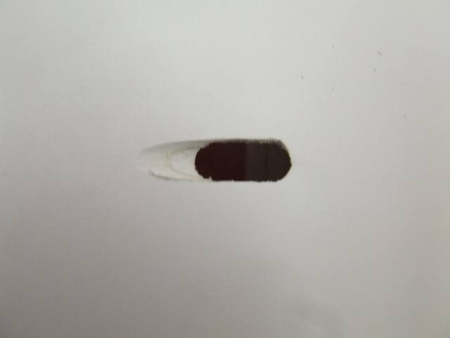 |
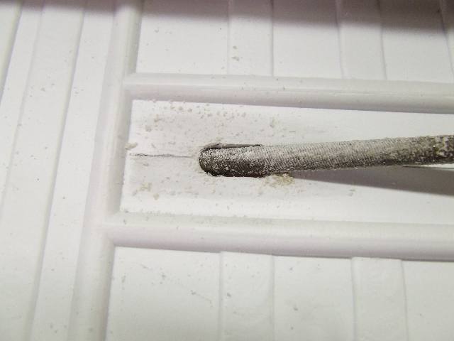
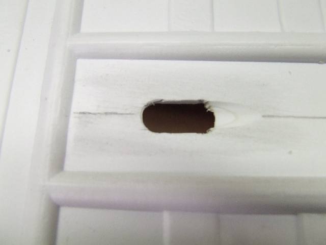
| Connect the two holes, then use a round file to bevel fore and aft of the hole. | Finished shaft pass-through from above. | Pass-through from below. |
 |
 |
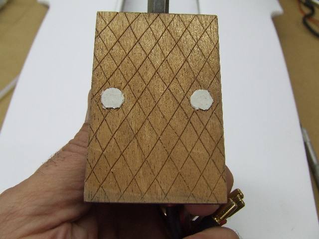 |
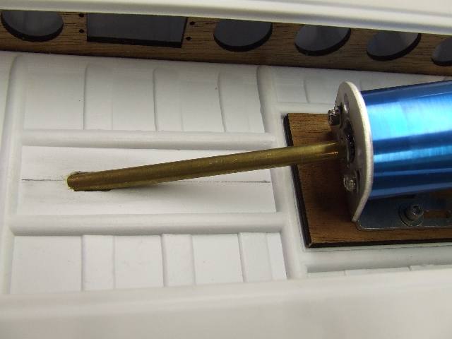
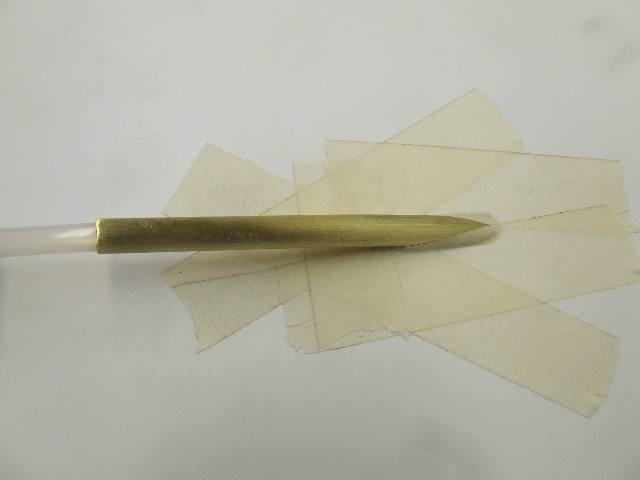
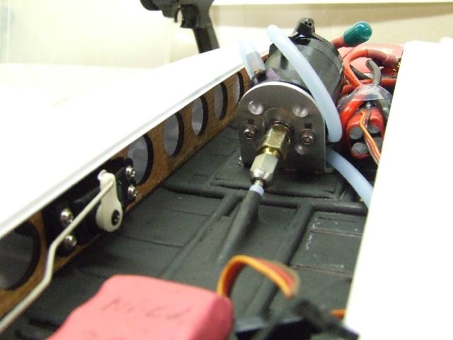
| Brass tube slipped over the shaft verifies correct location of the pass-through. Note: The aluminum motor mount is moved about 80% toward the bow of the boat at the slots where it bolts to the ply base. | Roughen the area around the shaft pass-through, and around the motor mount bed with 100 grit paper. | Sand and score the motor mount base for the best bond to the epoxy. Use small tape pieces to cover the blind nuts to keep out epoxy. |
 |
 |
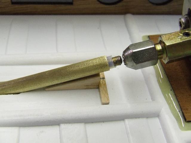 |
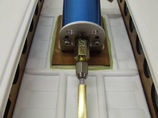
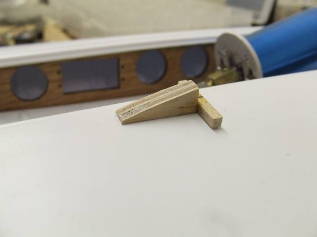
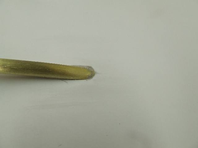
| Temporarily install flex shaft and liner and install shaft in the collet to verify alignment. With the mount screws tight, bed the motor and mount to the hull with filled epoxy and let it fully cure before proceeding. | Prepare wood scraps to build a shaft support. | Position the wood like this, to support the brass shaft tube. Note that the brass shaft tube is scuffed with sandpaper. |
 |
 |
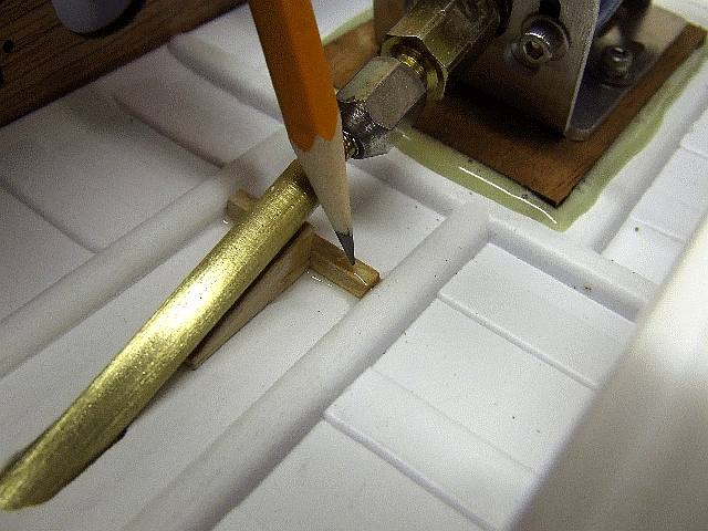 |
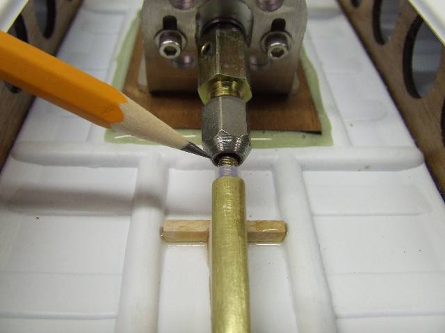
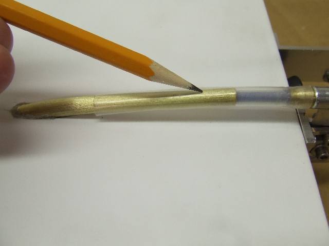
| Tape around the underside of the pass-through. | Insert the flex cable into the collet. Verify proper
alignment of the flex shaft to the collet.
|
Once centered, put a drop of CA at pencil point to tack the brace in place. This brace helps laterally stabilize the end of the tube and acts as a dam for the epoxy. |
 |
 |
 |
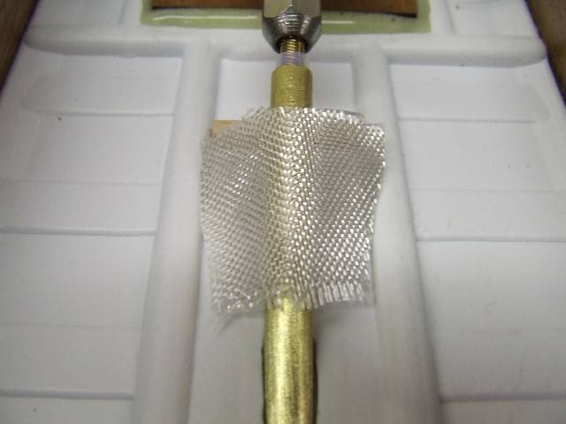
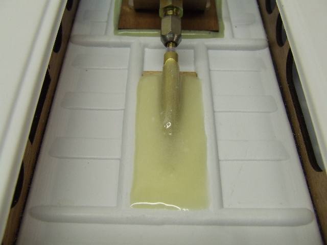
| Use a piece of fiberglass cloth to reinforce the flex-shaft tube brace. | Bed the pass through with filled epoxy and allow it to fully cure. | Remove the underside tape for a clean finish. |
 |
 |
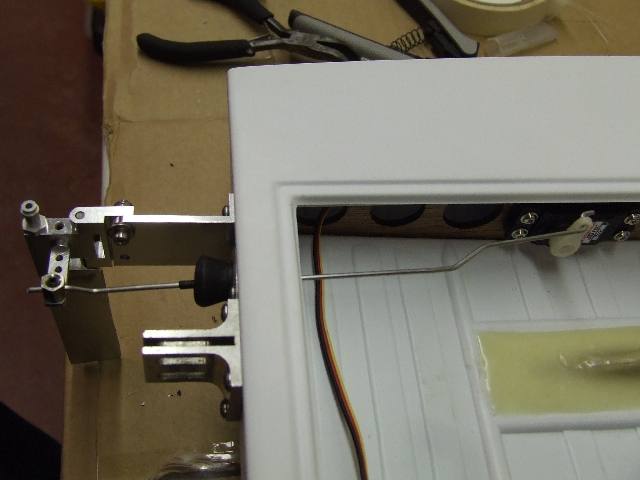 |
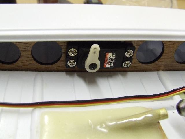
| Locate the rudder linkage hole with room for the two mounting screws for the Bru-Line pushrod boot. | Install your HiTec HS-225B mini servo in the pre-drilled opening. | Use Z-bends in the rudder pushrod to center it in the transom hole to avoid binding. |
 |
 |
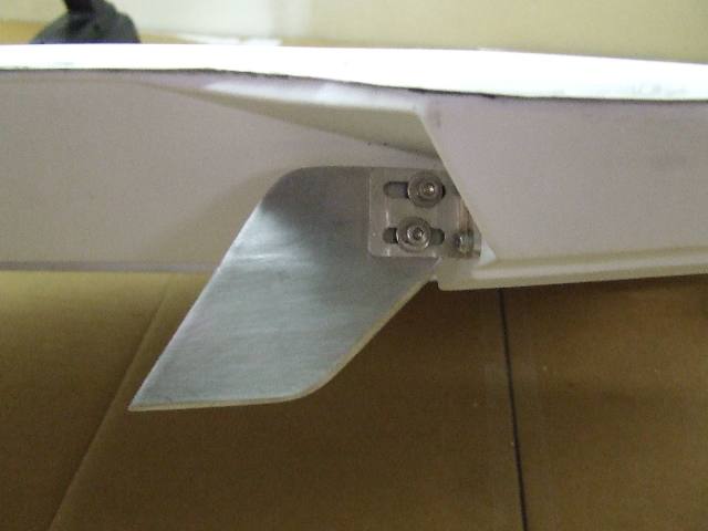 |
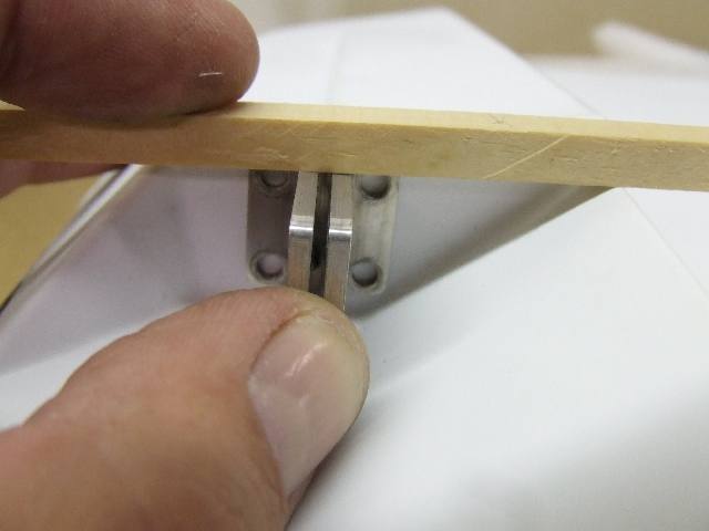
| Square the turn fin bracket to the bottom of the sponson. | The installed turn fin. | Side view showing location of bend. |
 |
 |
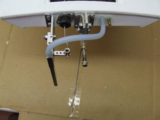 |
| Shield the plastic hull and install a piece of heat-shrink tubing between the stuffing tube and the strut. It keeps water out from between the liner and strut. Put a dab of CA at the front end of the shrink-tube to seal against water entering. | Locate two cooling tubes through the transom. Brass tube is 5/32 inches in diameter. | Silicone water pickup hose installed. IMPORTANT: In an accident, or if the boat flips, the water hose could contact the prop and be cut and you could loose your cooling. Shorten the hose, put an up-angle on the transom water inlet tube, or secure the hose to the top of the strut with a nylon pull-tie. If you can touch the prop with the hose, it can be cut! |
 |
 |
 |
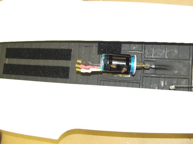
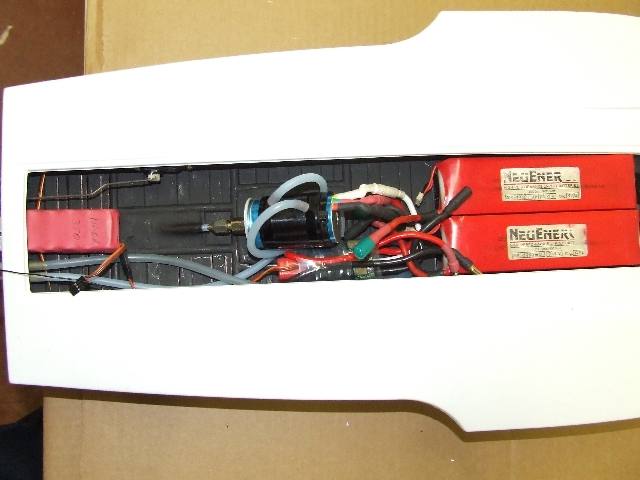
| Inside is painted with black enamel that doesn't show oil/grease. Velcro is "Industrial" type available at hardware store. | LiPoly batteries, motor, cooling lines, esc servo (recessed into the left hull), receiver (recessed into the right hull), and receiver pack installed. A small piece of soft EP foam (swim noodle) between the LiPoly packs and the carbon fiber brace at the bow can help prevent damage to the battery packs in a collision. | View from the rear of completed installation. |
 TM
TM